


“A9G Development Board: A Deep Dive into Features, Applications, and Hands-On Exploration for Next-Level IoT Projects!”


“Hey everyone, welcome back to blogs. Today, we’ve got something exciting to dive into — the A9G development board. This multi-functional board is based on the A9G GPRS/GSM+GPS/BDS module, and it’s here to help us explore the incredible capabilities of this technology.
Before we dive into the technical details, let me emphasize why the A9G development board is so exciting. This compact yet powerful board allows developers and enthusiasts alike to test and validate the essential features of the A9G module, paving the way for innovative applications in communication, tracking, and beyond.”
Features:
“Now, let’s talk about some of the amazing features packed into the A9G development board. It’s not just your ordinary board; it’s a powerhouse. We’ve got basic telephone and messaging functionalities, seamless GPRS network communication, and dual-mode GPS/BDS positioning. But wait, there’s more! The board also comes with lithium battery charging management, interfaces for microphone and speaker, USB communication, multiple user buttons and LEDs, TF card slot, acceleration sensor, SPI and I2C2 interfaces, and an ADC interface. That’s a lot, right? This board is truly versatile.”
“But why is this board so feature-rich? It’s all about flexibility and functionality. With basic telephone and messaging capabilities, you can explore communication possibilities. The GPRS network communication opens the door to IoT applications, enabling seamless data transmission. The GPS/BDS dual-mode positioning functions ensure accurate location tracking, which is crucial for a variety of applications.”
“ The lithium battery charging management system ensures efficient power usage, extending the device’s life. The inclusion of a microphone and speaker interface opens up possibilities for voice applications. USB communication makes it easy to connect to other devices. And with multiple user buttons and LEDs, TF card slot, acceleration sensor, SPI and I2C2 interfaces, and an ADC interface, the A9G development board becomes a versatile playground for creative minds.
Applications:
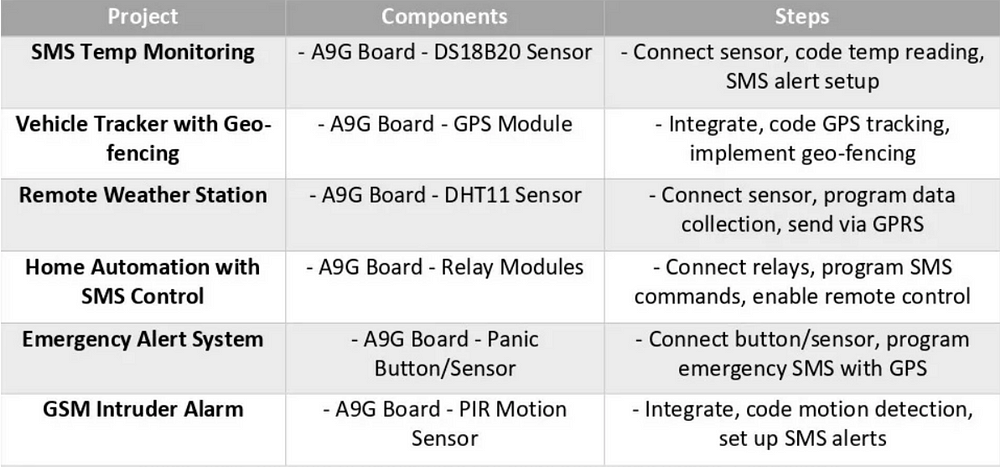
“Thinking about what we can do with this board? The possibilities are endless. Imagine creating a vehicle anti-theft device using GPRS+GPS and the acceleration sensor — now your vehicle is not just secure, but smart too. Or how about a remote monitoring intercom using GSM and microphone/speaker functionalities? That’s just scratching the surface. We could also design a smartwatch utilizing GPRS/GSM+GPS or an elderly monitoring watch for enhanced care. And if you’re into surveillance, a remote camera with GPRS+TF+camera expansion board is within your reach. The A9G development board opens up a world of potential.”
These are some of my ideas :
“Unlocking A9G Dev Board: From Vehicle Security to Smartwatches and Beyond! 🌐🚗⌚️
Consider this: a vehicle anti-theft device with GPRS+GPS and an acceleration sensor, making your vehicle not just secure but smart. Or picture a remote monitoring intercom using GSM, complete with microphone/speaker functionalities. But that’s just the beginning! How about a smartwatch with GPRS/GSM+GPS or an elderly monitoring watch for enhanced care? And for those keen on surveillance, imagine a remote camera with GPRS+TF+camera expansion board. The A9G development board opens doors to a world of possibilities, blending extensive features with real-world applications. Let’s dive into the exciting potential of this board!
other examples:
“Alright, let’s get hands-on with the A9G development board. First things first, we’ll look at the basic debugging wiring — connecting our board to various peripherals. Then, I’ll guide you through the power-on process, ensuring a smooth start. And for those who are keen on customizing the firmware, we’ll cover how to burn firmware onto the board. It might sound technical, but trust me, it’s easier than you think. Stick around, and we’ll get this board up and running in no time.”
Let’s get our hands dirty and explore how to operate the A9G development board. First, we need to understand the basic debugging wiring. Connecting the board to various peripherals is essential for testing and prototyping. Don’t worry; I’ll guide you through it step by step. Next, we’ll cover the power-on process. Ensuring a smooth startup is crucial for the proper functioning of the board and connected devices. And for the tech enthusiasts out there, burning firmware onto the board might sound complex, but fear not — I’ll break it down into easy-to-follow steps. By the end of this tutorial, you’ll be ready to unleash the full potential of the A9G development board.
Development board appearance and size:
Appearance :
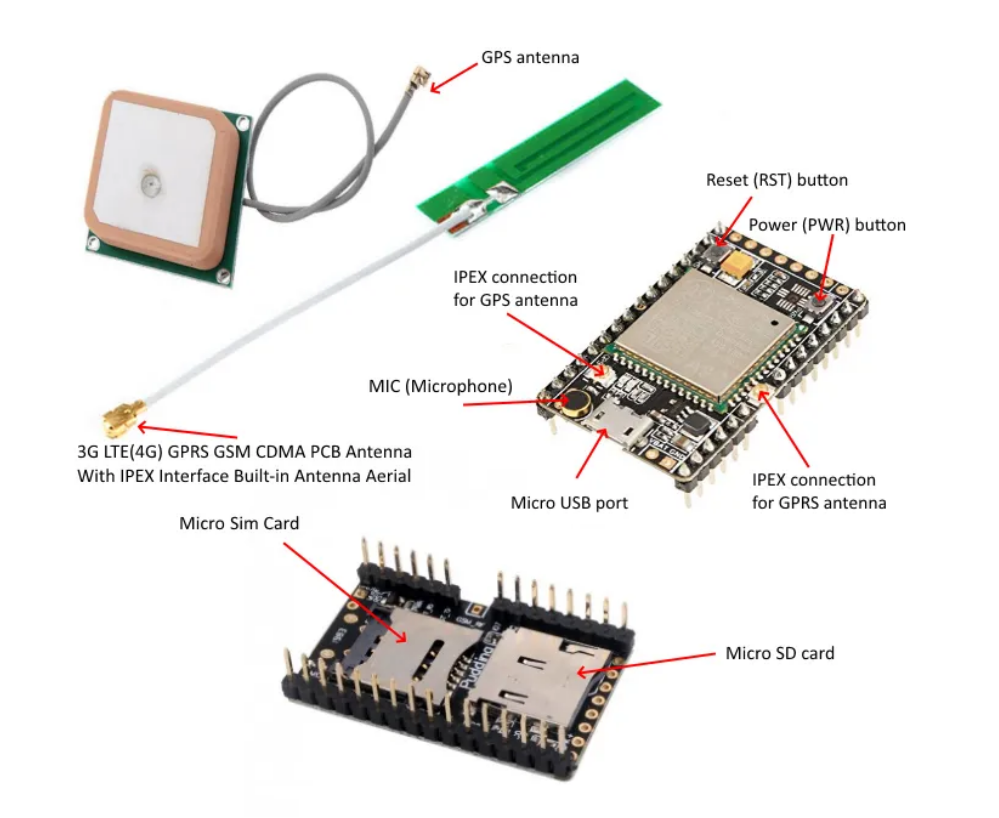
A9g Borad
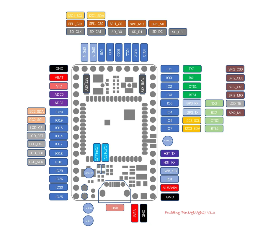
Pin Map
GPRS C SDK Build environment installation
1. Pay Attention
important, please read first
SDK does not have a specific IDE, and the user chooses the code editor to edit the code.
When modifying the code, you must not use the notepad and writing board that windows brings. Please use a more professional editor (recommended as VScode, sublime, atom, eclipse, source insight, or other editors you are familiar with. )
Please modify the editor settings. The end of the file symbol is set to UNIX style (
<LF>(\n) end), and file encoding isUTF-8if you are cloned using git, set the git at pull not to convert
<LF>to<CR><LF>, set the method reference here
2. Download tool chain, debug tool and SDK
Download CSDTK4.2: Baidu Cloud, MEGA Cloud, direct link
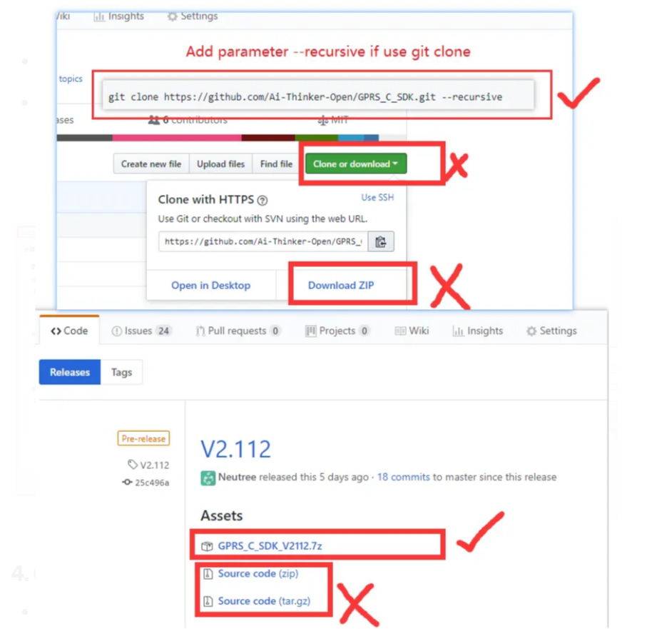
Get SDK
or clone by git :
git clone https://github.com/Ai-Thinker-Open/GPRS_C_SDK.git --recursive(pay attention--recursiveis needed, or compile will fail for lake of files)Check C_SDK
platform/csdkfolder, there should be some folders and file, if not, you may get source code with wrong way, check and download again
3. installation
Decompression to a folder, such as
C:\CSDTK, path please DO NOT bring Chinese!Run
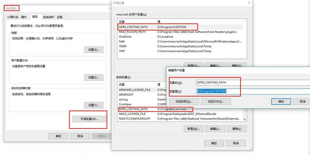
config_env_admin.batfile in CSDTK to set environment valueWhat the script does is to create an environment variable named
GPRS_CSDTK42_PATH, which has a variable directory value of CSDTK. If the script fails, you can build it by yourself
4. Compile
Decompress the CSDK downloaded to
GPRS_C_SDKfolder into a directory, such asC:\GPRS_C_SDK, use the underscore(_) instead of minus(-).Step into CSDK folder(
C:\GPRS_C_SDK),right click mouse in th blank space in the folder with shift key pressed, then open with powersheel of cmd.
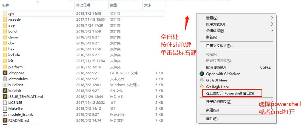
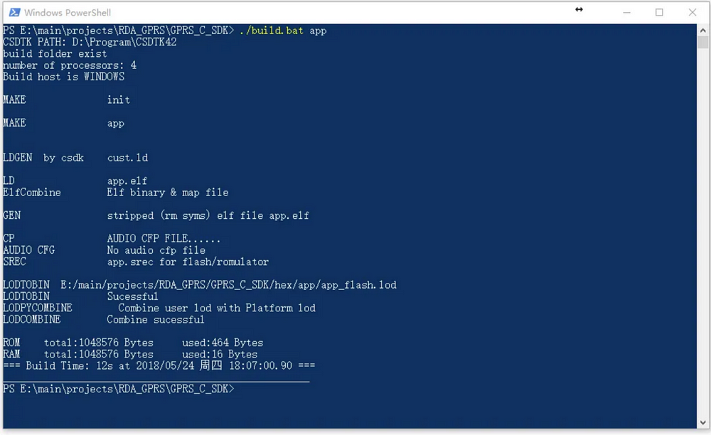
Type ./build.bat app or build.bat app to build app project, ensure our environment is ok.
If comes withNO CSDTKerror, you may need to restart you system(mostly appears on Win7).
Then you can use ./build.bat script to build project:
./build.bat $PROJ:compile app module,e.g.:./build.batsh appto compile the source code of app folder./build.bat demo $PROJ:compile demo project, e.g.:./build.bat demo gpioto compile gpio demo./build.bat clean $PROJ:clear the build files of$PROJ./build.bat clean all:clear all the build files./build.bat demo $PROJ release:build a release version, e.g.:./build.bat demo gpio release,if the last parameter is notrelease, it will be default todebugversion. The GDB can be used to debug errors after system crashed indebugversion, butreleaseversion can not, watch dog activate in release version,it will auto restart system when system crashed!
e.g.:
./build.sh demo gpio
A build folder will be generated after compile, there's two *.lod files in th hex folder, it's the target file that burn(download) to dev board
- about target hex file(*.lod)
There’s two hex file,(*_B*.lod and *_flash.lod), you must burn the bigger one to dev board at the first time, then you can just burn the little one to reduce the doanload time. And you must download the bigger if you update the SDK version
How to operate
Basic debugging
Wiring: The development board uses AT firmware. When debugging, use 4 wires to connect usb-ttl and connect to the computer for debugging: VUSB→5V; GND→GND; AT_TX→RX; AT_RX→TX;
Or use USB for power supply, and connect three more lines GND→GND; AT_TX→RX; AT_RX→TX;
Or lithium battery power supply VBAT→(3.3v-4.2)V; GND→GND; AT_TX→RX; AT_RX→TX; (To use VBAT power supply, you need to press the power_key button for about 2s)
Power on
The A9G development board can be powered by lithium batteries or USB.
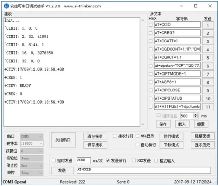
The module will run automatically after power-on for 1~2S, and the serial port will automatically output information at this time. The entire process from power-on to normal operation of the development board does not require any operation.
To reset, please press the Rst_Key button.
The module enters AT command mode by default.
Power-on print output information
“As we wrap up today’s blog, we’ve covered a lot of ground with the A9G development board. From its impressive features to a myriad of applications and hands-on operations, it’s clear that this board is a game-changer in the world of IoT. The ability to combine basic communication, GPS tracking, and a multitude of peripherals makes it a go-to for prototyping and development. Whether you’re into smart devices, security, or monitoring solutions, the A9G development board has got you covered. Stay tuned for more exciting explorations into the world of technology right here on blog. Don’t forget to like and hit that notification bell so you never miss out on the latest tech adventures. Until next time, happy coding!”
This blog has been written by Akshay Chame (LinkedIn, GitHub, Medium).